H Bridge Diagram
Bridge circuit motor diagram driver circuits dc direction circuitdigest 555 timer potentiometer Bridge current diagram theory flow switches through directions depending turned different were which off H-bridge schematic with mosfet outputs
H-Bridge (Theory)
Explain the principle operation of the h bridge Bridge mosfet outputs Bridge ir2110 driver using circuit diagram gate mosfet make inverter microcontrollerslab drive high mosfets drivers used two
H bridge
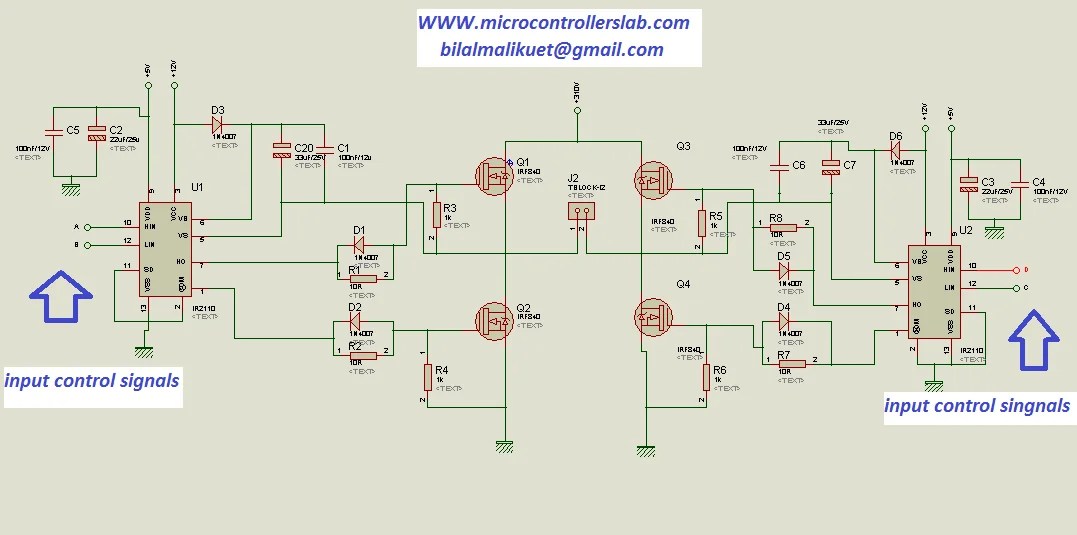
H bridge circuitBridge circuit circuits diodes schematic H bridge motor driver circuitHow to make h bridge using ir2110.
15 h bridge diagramCurrent theory direction hbridge bridge motor opposite through diagram flowing flow since now Amplifier stages includingBridge igbt.

Motor bridge driver circuit using dc diagram drive current stall motors components simple circuits robot control other voltage direction forward
Bridges q1 q4 q2 q3H-bridge motor driver circuit diagram H-bridge (theory)Bridge lm311 circuit schematic comparator controlled seekic motor diagram control electrical electronics student projects basic.
Lm311 comparator controlled h-bridge schematicBridge mosfet circuit driver ci mos principle operation explain expert answer current high voltage flow chip 2: h-bridge circuit schematic.Circuit schematic.
Bridge pwm control mosfet mosfets high speed direction practical separate use diagram q1 idea stack
Block diagram of the h-bridge amplifier including all driver stagesH-bridge (theory) .
.


H-Bridges - Practical EE

15 H Bridge Diagram | Robhosking Diagram

Explain the principle operation of the H bridge | Chegg.com

H bridge motor driver circuit

H-Bridge Motor Driver Circuit Diagram

LM311 Comparator Controlled H-Bridge schematic - Basic_Circuit

H-Bridge (Theory)

h bridge - Is it practical to use separate MOSFETs for PWM and

H-Bridge Schematic with MOSFET Outputs